Wiring diagram help

Sat May 22, 2010 11:58 am

So unfortunately they didn't teach me how to draw a wiring diagram or do complicated wiring in social work school, so I kind of made this up as I went along based on my reading. Does this look like it would work to you electrically smart people?

Image

Main components are as follows:

Auber Universal 1/16 DIN PID Temperature Controller - http://www.auberins.com/index.php?main_ ... cts_id=106"

Auber Liquid tight RTD sensor x 2 - http://www.auberins.com/index.php?main_ ... ucts_id=96"

Auber multifunction timer, counter, tachometer - http://www.auberins.com/index.php?main_ ... cts_id=115"

1/4" Solenoid Valve x 3 (for pilots)

1/2" Solenoid Valve x 3 (for main burner)

Honeywell Q373A2115 Intermittent Pilot Burner Igniter x3 (I'm thinking I will manually fire these with switches - I'm not sure how to wire them to auto fire with the solenoids)

I appreciate any guidance on this. I'm designing a 2 tier Brutus inspired system that will fit in my Honda Accord.
eww
 
Posts: 13
Joined: Wed May 06, 2009 9:37 pm

Re: Wiring diagram help

Sun May 23, 2010 1:29 pm

No, what you have will not work. First off, prepare to spend some bank. Those intermittent pilot units are ex$pen$ive. I got lucky and found one for $100, but expect to pay $150-$200 each. They also require 24VAC power to operate - so you'll need a transformer. They have their own relays built into their logic, so they take care of the lighting of the pilots automatically. All you have to do is supply them with gas and 24 volts, and they will light the pilot, then light the main.

If $500 seems to expensive for you for your pilot automation (just for the honeywell units!) - then you will need to consider basic solenoid gas valves and standing pilots. IMHO, you do not need to automate the boil kettle burner. Not only will you be forced to use a low pressure wok burner (not adjustable), but your are basically boiling or not... when would you ever set it to "not boiling"? It basically is on or off. I went with a solenoid valve, and a piezo electric ignitor - just for convenience.

Ok, back to the issues.... the ASCO solenoid valves come in 110VAC and 24VAC... you need to know which ones before we can help you with your diagram. If you get the 24VAC ones, then you can use the same transformer as for the Honeywell(s).

The next thing to work on in your diagram is the switches. You show breaking both conductors with "double pole, single throw" switches. Instead, make sure each device has a path back to neutral, and put a "single pole single throw switch" (or the contacts on the auber PIDS - 4 & 5) on the hot leg. Obviously keep the 24V and 110V circuits separate.


Mylo
"Life is too short to bottle homebrew." - Me

"HEINEKEN? Fuck that shit! Pabst Blue Ribbon!!!" - Dennis Hopper, in Blue Velvet
User avatar
Mylo
Global Moderator
 
Posts: 4722
Joined: Tue Oct 09, 2007 10:50 pm
Location: Scottsdale, AZ

Re: Wiring diagram help

Mon May 24, 2010 10:35 am

Thanks for the reply Mylo I really appreciate it. I'm taking my time on this since it is really outside of my scope of practice.

I got 6 solenoids given to me from a friend who got them from me from work - they have Viton seals so should be good to go. The three 1/2" solenoids that I would be using on the main burners are 24 VAC and the three 1/4" are 120 VAC. I just got them yesterday and noticed the voltage, so I'll have to rework the wiring to include some transformers. If I use a 120 VAC input / 24 VAC output transformer to step down the power supply for the solenoids do I have to do anything special on the neutral return before it hits the GFCI?

After I posted this I did some more research on the pilot assembly I posted above. Per Honeywell it needs 15,000V ... I ain't messing with that. The system I'm building will have the burners pretty low to the ground, so I'm looking for a way to fire the pilots without laying on the ground to do so. As of right now I'm thinking about modifying the Honeywell pilot assembly to use gas grill push button piezoelectric devices to generate an ignition spark for the pilots. I'm planning to use low pressure banjo burners, so I'm not concerned with the solenoid on the BK. Thoughts on this?

RE: Switches: I thought that if I wired it in parallel off a main 120 VAC trunk line I could use double pole/single throw switches without an issue because there would always be a neutral return in the circuit. If I understand your post correctly this is not the case.

Also, how big of a concern is stepping down amperage in a system like this and what's the best way to do this?
eww
 
Posts: 13
Joined: Wed May 06, 2009 9:37 pm

Re: Wiring diagram help

Mon May 24, 2010 3:32 pm

Here's working diagram v. 2.01

The bold gray lines are my "trunk" and seem to complete a circuit (to me at least) which would allow the double pole switches. I would appreciate any/all feedback on this.

Image

Thanks again!
eww
 
Posts: 13
Joined: Wed May 06, 2009 9:37 pm

Re: Wiring diagram help

Mon May 24, 2010 7:09 pm

eww wrote:Thanks for the reply Mylo I really appreciate it. I'm taking my time on this since it is really outside of my scope of practice.

I got 6 solenoids given to me from a friend who got them from me from work - they have Viton seals so should be good to go. The three 1/2" solenoids that I would be using on the main burners are 24 VAC and the three 1/4" are 120 VAC. I just got them yesterday and noticed the voltage, so I'll have to rework the wiring to include some transformers. If I use a 120 VAC input / 24 VAC output transformer to step down the power supply for the solenoids do I have to do anything special on the neutral return before it hits the GFCI?

After I posted this I did some more research on the pilot assembly I posted above. Per Honeywell it needs 15,000V ... I ain't messing with that. The system I'm building will have the burners pretty low to the ground, so I'm looking for a way to fire the pilots without laying on the ground to do so. As of right now I'm thinking about modifying the Honeywell pilot assembly to use gas grill push button piezoelectric devices to generate an ignition spark for the pilots. I'm planning to use low pressure banjo burners, so I'm not concerned with the solenoid on the BK. Thoughts on this?

RE: Switches: I thought that if I wired it in parallel off a main 120 VAC trunk line I could use double pole/single throw switches without an issue because there would always be a neutral return in the circuit. If I understand your post correctly this is not the case.

Also, how big of a concern is stepping down amperage in a system like this and what's the best way to do this?


The 15K volts needed for the Honeywell is generated internally. That's the spark circuit, and you don't have to mess with that. Just supply it with 24 volts, and it will take care of itself.

Banjo burners are not low pressure. Only the "wok style" (with the 19 or so tips) are - and if you use the honeywell setup - you have to use the low pressure burner. It works great for the HLT - as it is basically ON or OFF. You will have to get a dedicated low pressure regulator for the wok burners. My single tier has a gas beam (a la Brutus) that is fed with high pressure, and I put my low pressure regulator after it, but before the honeywell.

It doesn't make sense to automate burners that have the piezo electric ignitors (and it is seriously dangerous!), as you will have to manually ignite them by pushing a button. Your only choice for automated burners is 1) a standing pilot, or 2) a honeywell, intermittent pilot setup. If you use a standing pilot, then you can use your 24VAC solenoids. If you use the honeywell, it has the logic and solenoids built in.

There will be two wires on the 110V side of the transformer (hot and neutral). There will also be two wires on the 24V side. Use one for hot, and one for neutral (even though they are not color coded white and black). You do not want to route the 24V neutral back to the 110V. They are separate.

I'd send you my analog electrical design that I did for my system, but I think it might just confuse you (and it's pretty specialized for two burners, and assumes a HERMS circuit for mash adjustment). Again, you don't need to break both poles on any loads. Just the hot.

Make a decision on how many honeywells and/or standing pilots you are going to use, and I'll see if I can whip up a quick schematic for you.


Mylo
"Life is too short to bottle homebrew." - Me

"HEINEKEN? Fuck that shit! Pabst Blue Ribbon!!!" - Dennis Hopper, in Blue Velvet
User avatar
Mylo
Global Moderator
 
Posts: 4722
Joined: Tue Oct 09, 2007 10:50 pm
Location: Scottsdale, AZ

Re: Wiring diagram help

Mon May 24, 2010 9:20 pm

Don't take the following comments as argumentative ... I'm just attempting to understand.
Mylo wrote:Banjo burners are not low pressure. Only the "wok style" (with the 19 or so tips) are - and if you use the honeywell setup - you have to use the low pressure burner. It works great for the HLT - as it is basically ON or OFF. You will have to get a dedicated low pressure regulator for the wok burners. My single tier has a gas beam (a la Brutus) that is fed with high pressure, and I put my low pressure regulator after it, but before the honeywell.
Mylo

On some sites the banjo is listed as low pressure and it's listed as high on others (the manufacture lists it as high, so I think you're right on this). However, I've read accounts of others using the banjos on low pressure without issue. This is something I need to look into more before making my final decision.
Mylo wrote:It doesn't make sense to automate burners that have the piezo electric ignitors (and it is seriously dangerous!), as you will have to manually ignite them by pushing a button. Your only choice for automated burners is 1) a standing pilot, or 2) a honeywell, intermittent pilot setup. If you use a standing pilot, then you can use your 24VAC solenoids. If you use the honeywell, it has the logic and solenoids built in.
Mylo

...or 3) a standing pilot that is fired only when needed (so I don't need to get down on the ground to light the pilot after I have the pots in place). In my proposed design it's only the pilots that would be fired by the piezos. The gas for the pilots will be operated on a different switch and solenoid then the gas for the main burner. The main burners will be tied into PID ... not the pilot. I don't see how this is any more unsafe then commercial gas grills, but maybe I'm missing something.
Mylo wrote:There will be two wires on the 110V side of the transformer (hot and neutral). There will also be two wires on the 24V side. Use one for hot, and one for neutral (even though they are not color coded white and black). You do not want to route the 24V neutral back to the 110V. They are separate.
Mylo

I'm aware of basic wiring, but this just doesn't make sense to me. No matter how you wire it, the 24 VAC neutral circuit will eventually lead back to the 120 neutral circuit since that is what comes from the source/wall. If it's going through the transformer why should it matter where it re-enters the 120 VAC loop?
Last edited by eww on Tue May 25, 2010 4:58 am, edited 1 time in total.
eww
 
Posts: 13
Joined: Wed May 06, 2009 9:37 pm

Re: Wiring diagram help

Mon May 24, 2010 9:34 pm

Sharing my Wiring Diagram. I am amazed by the cost thus far for the electrical equipment. Just the distribution blocks for the 240V cost $20 each, for 4 legs.

Image

http://i966.photobucket.com/albums/ae14 ... 1Model.jpg
Conical Fermenter - Amber Lager
Keg#1 Dunkel
Keg#2 Helles
Keg#3 Flanders Red
Keg#4 Star San
Keg#5 Star San
Keg#6 Star San
User avatar
Kbar
 
Posts: 984
Joined: Tue Nov 11, 2008 4:43 pm
Location: Portland, Oregon

Re: Wiring diagram help

Wed May 26, 2010 5:04 am

eww wrote:On some sites the banjo is listed as low pressure and it's listed as high on others (the manufacture lists it as high, so I think you're right on this). However, I've read accounts of others using the banjos on low pressure without issue. This is something I need to look into more before making my final decision.


Don't confuse LP (liquid propane) with low pressure. That might be your mistake. No offense taken. You might be able to drill out the jet for a larger volume (at the lower pressure), but you will probably have fuel/air mixture issues.

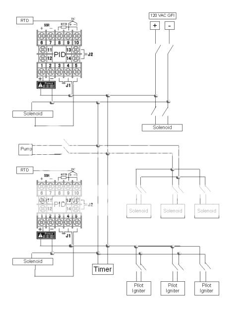
eww wrote:...or 3) a standing pilot that is fired only when needed (so I don't need to get down on the ground to light the pilot after I have the pots in place). In my proposed design it's only the pilots that would be fired by the piezos. The gas for the pilots will be operated on a different switch and solenoid then the gas for the main burner. The main burners will be tied into PID ... not the pilot. I don't see how this is any more unsafe then commercial gas grills, but maybe I'm missing something.


Ok, I see where you are getting at now. I would argue that this is just the standing pilot solution with some built in convenience. I might suggest simplifying slightly and just feed all the pilots off of one solenoid, and have one piezo spark at all three locations. Piezos come it two flavors - mechanical and electrical. I prefer the electrical that continue to spark as long as you hold it down. The mech. ones just spark once for each push.

One thing to keep in mind is that standing pilots are prone to blowing out, and then you risk a eyebrow eliminating boom when the PID turns on your main and the pilot is out (but the burner next to it is on). I'm pretty sure you can put a thermocouples on each pilot to safeguard against that, though - and I would highly recommend that.

FYI, my answer to this problem was to go with only two burners - one wok burner for the HLT (fired with a Honeywell), and one banjo burner for the boil. I utilize a HERMS coil (which I use later as my chiller) to do step mashing. I am still working on my automation, but I will control the both the HLT burner and the mash pump with PIDs of some kind. The boil kettle does have an ASCO valve and piezo ignitor, but again that's just for convenience.

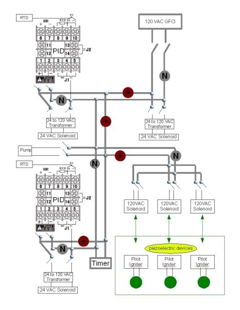
eww wrote:I'm aware of basic wiring, but this just doesn't make sense to me. No matter how you wire it, the 24 VAC neutral circuit will eventually lead back to the 120 neutral circuit since that is what comes from the source/wall. If it's going through the transformer why should it matter where it re-enters the 120 VAC loop?


The two low voltage leads are a separate circuit. The coils of high voltage induce a current in the secondary coil - but they are for all intents and purposes isolated. You can use a common ground for all DC, not AC.

So now I have enough to understand what you are doing, and I'll take a stab at a diagram.


Mylo
"Life is too short to bottle homebrew." - Me

"HEINEKEN? Fuck that shit! Pabst Blue Ribbon!!!" - Dennis Hopper, in Blue Velvet
User avatar
Mylo
Global Moderator
 
Posts: 4722
Joined: Tue Oct 09, 2007 10:50 pm
Location: Scottsdale, AZ

Next

Return to Brewing Sculptures

Who is online

Users browsing this forum: No registered users

A BIT ABOUT US

The Brewing Network is a multimedia resource for brewers and beer lovers. Since 2005, we have been the leader in craft beer entertainment and information with live beer radio, podcasts, video, events and more.